The combustion chamber of a waste incineration boiler is exposed to corrosive atmosphere where the temperatures can reach up to 1'400°C. It is obvious that the boiler walls must be protected accordingly.
You may have wondered how a waste incineration boiler can withstand high temperatures, the chemical attack and abrasion.
This is based on decades of experience and material development in this field.
The heat transfer from the furnace to the steam boiler circuit is conducted through refractory linings in the furnace/first boiler pass and the other boiler passes. The lining is necessary to protect the steel walls, called membrane walls, from chemo-corrosive and abrasive attack by the hot combustion gases.
Boiler sections being exposed to different kinds of corrosion
- In the furnace the temperatures are between 1’000°C and 1’400°C. The unprotected steel walls would be attacked by high temperature corrosion due to oxidation, abrasion and corrosion. Accordingly, the walls must be protected by fireproof linings.
- The first boiler pass begins at the end of the furnace, above the last secondary air injection. For regulatory reasons, a flue gas temperature of at least 850°C must be maintained for 2 seconds up to the boiler ceiling. As well here, the unprotected steel walls are exposed to high temperature corrosion. Due to the concentration of heavy metal compounds and halides, depositions of molten slag and salts are to be expected.
- Above the 850°C/2-second limit, rapid heat dissipation must be ensured. The inlet temperature to the second pass must be accordingly low in order to moderate the inflow temperature to the superheater in the second and third pass and by this to keep corrosion as low as possible.
- Due to the low corrosion below 650°C, unprotected steel can be used in the other boiler passes.
- Below 170°C, electrochemical corrosion takes place due to condensation of various halides and heavy metals and the use of steel is no longer possible.
Materials for the Protective Lining
Suitable fire-resistant materials are ceramic materials (refractory concrete / chamotte) based on aluminium oxide (Al2O3) with different heat transfer resistances (insulating) or silicon carbide (SiC) plate systems or masses with good heat transfer properties.
The fireclay has a mortar consistency and is usually used as masses for layering, backfilling or gunning.
The silicon carbide tiles are sintered in a pre-defined form with a thickness of about 30 mm and thus obtain a smooth and low-pore surface. Thanks to their good thermal conductivity properties and high temperature resistance, these systems can be used precisely for highly stressed furnaces.
Excellent corrosion protection with good thermal conductivity properties and resistance to abrasion is achieved by cladding with Inconel.
Inconel (alloy 625, material no. 2.4831) is a nickel-based alloy, which is welded in an inert gas atmosphere onto steel surfaces in a thickness of approx. 2 mm as welding wire.
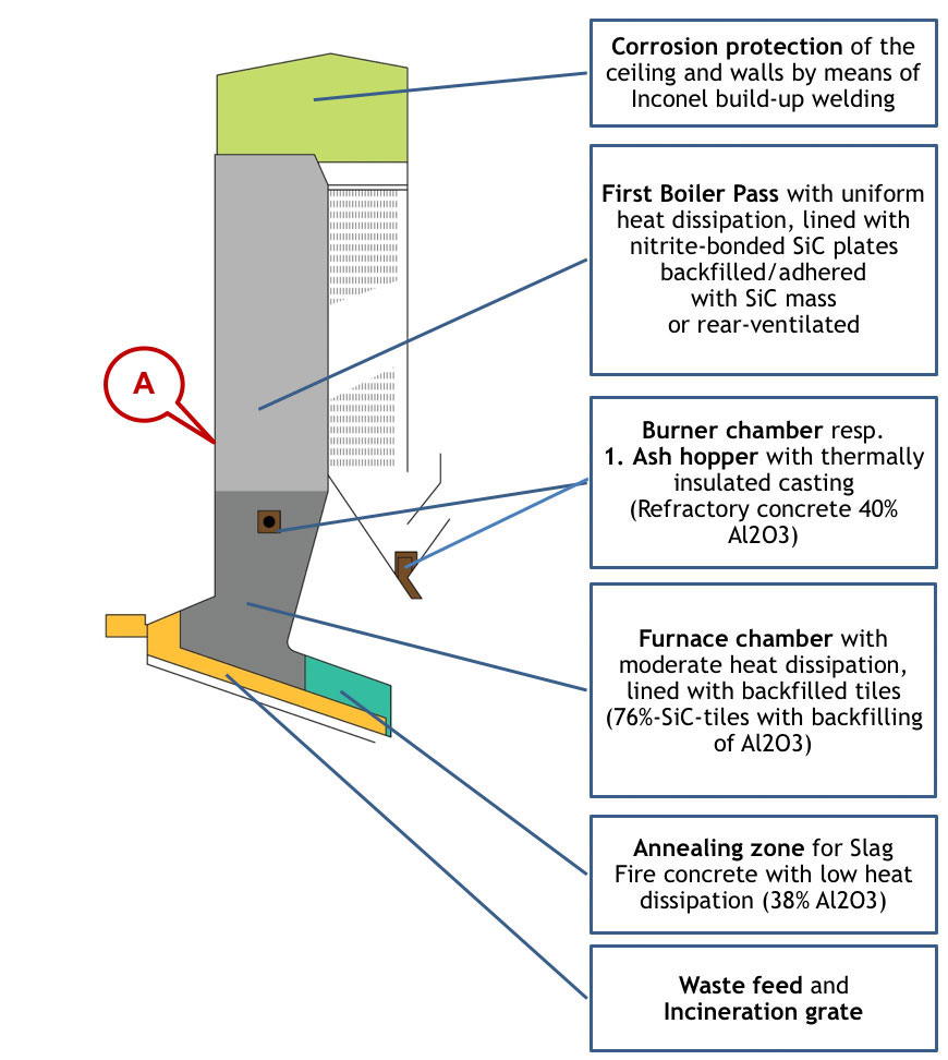
The main zones of a Waste Incineration Boiler
In the following, a typical structure of a waste incineration boiler is presented:
Graphics by Explosion Power GmbH
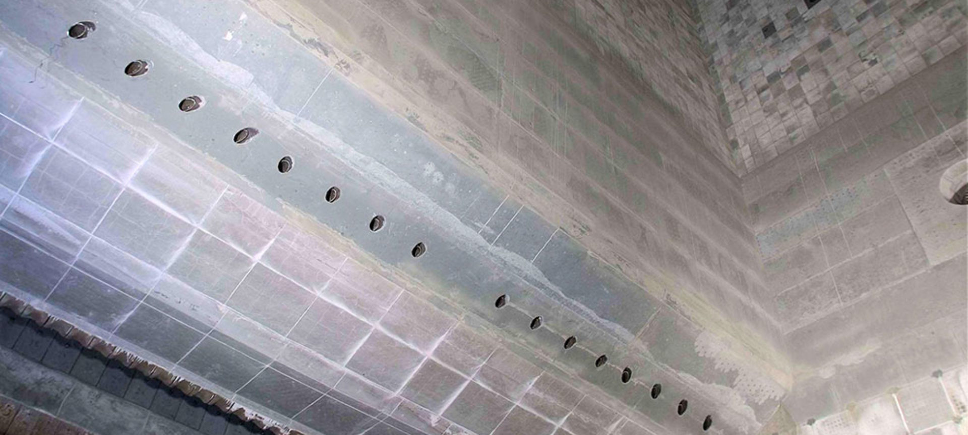
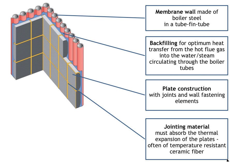
View on section „A“ of the Fig 1:
See in the section of the first boiler pass the construction of an installed plate lining.
How is the heat dissipated from the fire?
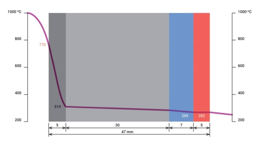
In the following diagram we consider a temperature profile of the heat flow from the hot flue gas into the tube being flushed by circulating water/steam.
- Assumed is flue gas temperature of 1000°C. The outer surface is “cooled” from the back, which reduces its surface temperature to approx. 770°C.
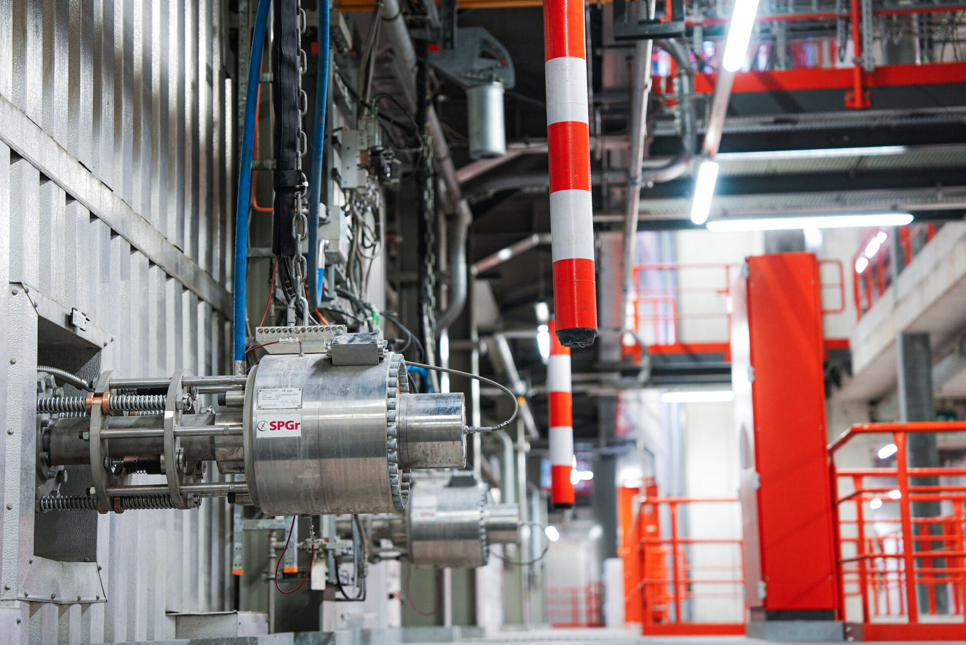
- The ash particles form a layer of approx. 5 mm, which has a strong insulating effect. This reduces the temperature to approx. 310°C. Consequently, it shall be achieved to keep this coating as small as possible. By means of the Shock Pulse Generators (SPG) of Explosion Power GmbH, the deposits can be effectively kept small.
- The SiC plates have good thermal conductivity properties which cause a small temperature reduction. In our case from 310°C to 265°C.
- The material of the backfilling, alternatively the space of a rear-ventilation in a gap of approx. 7 mm, reduces the temperature only insignificantly.
- The tube wall is well heat conducting and therefore, the heat transfer can be transferred with low temperature loss into the tube through which water/steam flows.
- It is assumed that the pressure in the water/steam system of the boiler drum is 47 bar, which corresponds to a saturation temperature of 260°C.
Literature sources:
Thomè-Kozmienski, K.J. und Beckmann M.: Energie aus Abfall, Band 8 und 10, TK Verlag
Mokesa: Wärmetechnische Optimierung durch gezielte Auswahl vor Feuerfestsystemen
Saint-Gobain: Refractory solutions
Jünger + Gräter Refractories: Brochures