Everyone knows them, everyone fears them: overheating corrosion in waste incineration plants. 4 causes all operators know - at the latest after reading this article.
The real problem is actually the loss of material suffered by superheater heat exchanger tubes due to corrosion. If the walls of the tubes (which may be pressurized to 40 bar) drop below a minimum thickness, they will rupture during operation and the boiler will have to be shut down. High levels of repairing cost and reduced revenue due to the unplanned downtime are the final consequences. If the loss of material is detected during planned downtime by carrying out wall thickness measurements, the damaged tubes can be replaced foresightedly (see Figure 1). Thus, superheater corrosion has a direct impact on the maintenance costs, availability and traveling period of a Waste to Energy plant.
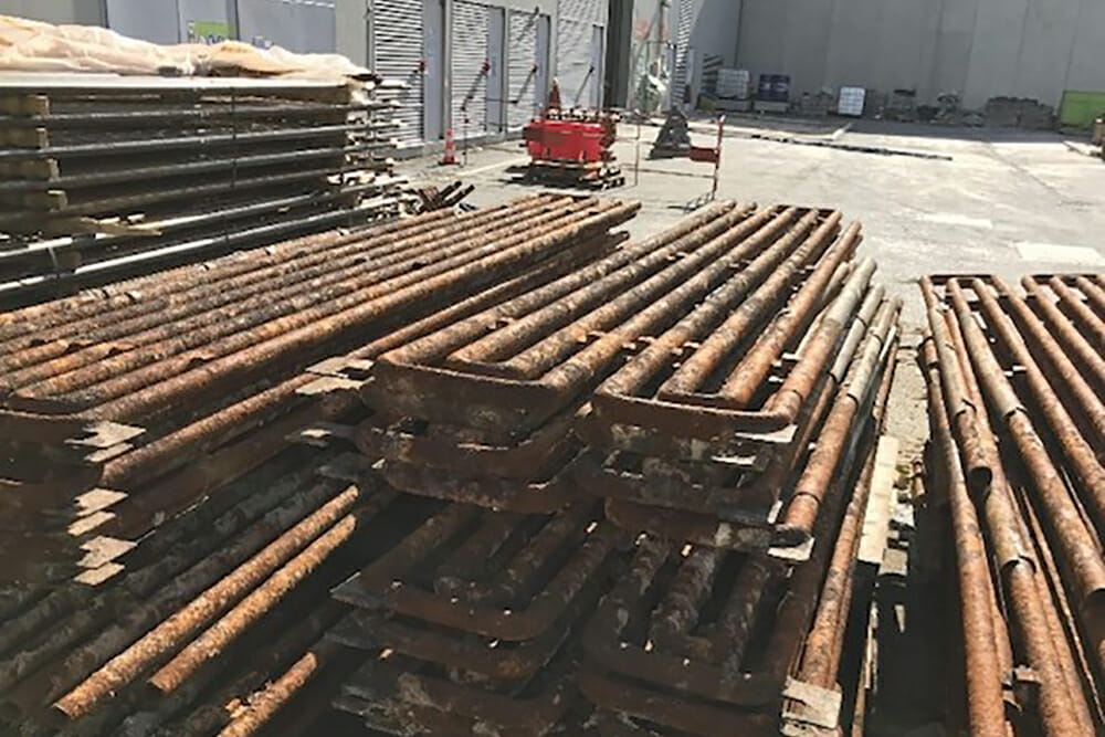
be replaced.
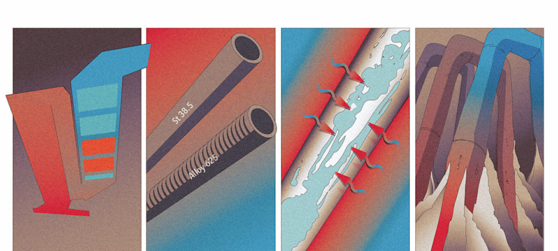
Superheater corrosion is mainly caused by chlorine coming into contact with the outer wall of the tube [1]. Corroded pipes show several layers: a thin layer of iron chloride (FeCl2) forms directly on the outer wall of the tube, followed by an iron oxide (Fe2O3) layer and lastly a layer of fly ash build-up. The corrosion that occurs during operation is a cyclic process: chlorine (in the form of HCl aerosols, Cl2 molecules and chlorides in fly ash particles) and gaseous oxygen enter the outermost layer of fly ash build-up from the flue gas side. Chlorine and oxygen then diffuse through the build-up layer into the iron oxide layer. At the boundary between the iron oxide and iron chloride layers, the oxygen replaces the chlorine in the iron chloride. Iron oxide is thus produced and the displaced chlorine is released in the form of (FeCl3)2. This diffuses back to the tube surface because the chlorine concentration is already high enough from the other direction. Iron is then released again from the metal matrix at the surface of the tube. This cyclic process takes place more particularly within a temperature range of 250–550°C – the reaction rates are too low at temperatures outside of this range [2].
What are the implications for operating a Waste to Energy plant? Four causes are of great importance for superheater corrosion.
Cause 1: Poor boiler design
The boiler design and steam parameters directly affect the temperature in the corrosion product and ash layers that form on the superheater tubes. The temperature determines the speed of the reaction and the transport processes within the layers. The extended Flinger corrosion diagram [3] allows the influence of the arrangement of the heat exchanger bundles in the boiler and their connection to be displayed and thus critical areas to be identified.
Cause 2: Superheater tube material is not sufficiently resistant
As well as the external temperature of the tube, the tube material also plays an important role. The iron atoms in general-purpose structural steels (such as St35.8) react more quickly to chlorine because they are less well protected than in tubes made from stainless steel. This material, which is used in the chemical industry, would be ideal for the tubes. However, manufacturing heat exchanger bundles from stainless steel is just too expensive. That is why plant operators and manufacturers started making heat exchanger bundles – which are critical from a corrosion perspective – from a more robust type of alloy steel or started protecting them with cladding made from nickel-based materials such as Alloy 625 (see Figure 2). This additional layer reduces corrosion from occurring directly on the tube surface.
Cause 3: Unfavorable local velocity profiles for flue gases
The local velocity profile of the flue gases affects the local heat flux to the superheater tubes and affects the build-up of fly ash on the superheater tubes. The higher the flue gas velocity, the higher the heat flux and the higher the temperatures in the layers on the surface of the superheater tubes. As the build-up grows or constantly renews itself, the amount of chlorine and oxygen available in the layers on the surfaces of the superheater tubes also increases.
Cause 4: Uncontrolled fouling in the heat exchanger bundles of superheaters
As explained above, the new chlorine and oxygen that feed the corrosion process actually stem from the growth or constant renewal of the fly ash layer, well known as fouling. What’s more, if the build-ups become excessive, bridges may form between the tubes, thereby closing certain areas of the heat exchanger bundle completely. The available cross-sectional area of the superheater becomes smaller, the flue gases are diverted and higher flue gas velocities are generated locally – which takes us back to cause 3.
Conclusion: How to prevent superheater corrosion in your Waste to Energy plant
To identify superheater tubes that have already been attacked by corrosion, you must carry out measurements (of wall thicknesses, degradation rates) and take samples locally – both during operation and planned downtime. A possible approach for this is described under [4].
Anyone wishing to reduce superheater corrosion must cast a critical eye over their plant to check for the four causes described above. Cause 1 can, be countered by carrying out additional cleaning of the radiation passes to lower the flue gas temperature in the superheater area. By doing so critical (with respect to corrosion) heat exchanger bundles are moved into a non-critical area. In the case of cause 2, tubes that are particularly susceptible can be protected in the future by using a different material or cladding. As regards causes 3 and 4, areas of heat exchanger bundles can be modified by means of removing tube rows.
Or fouling is cleaned online and permanently by means of additional boiler cleaning equipment – heat exchanger surface stays therefore open permanently.
List of references:
[1] Maisch, S.: Korrosion in Anlagen zur thermischen Abfallbehandlung – Weiterentwicklung und Optimierung einer online Korrosionssonde., 2010
[2] Warnecke, R.: Fünfzig Jahre und kein bisschen weise – Korrosion und Verfahrenstechnik in thermischen Abfallbehandlungsanlagen, 2014
[3] Aleßio, H.P.: Korrosion ohne Chemie? – Erläuterungen zum Hintergrund und zur Nutzung von Korrosionsdiagrammen, 2014
[4] Molitor, D.: Erfahrungen aus zwanzig Jahren Revisionsbegleitung, 2017